Clippers Diagram / Andis Product Documentation / These circuits perform two fu.
Dapatkan link
Facebook
X
Pinterest
Email
Aplikasi Lainnya
Clippers Diagram / Andis Product Documentation / These circuits perform two fu.. Clipper circuits are basically termed as protection devices. Clippers find extensive application in radar, digital and other electronic systems. And at the same time, the ac signal does not distort the remaining part of the waveform. Andis clipper diagrams oster clipper diagrams wahl clipper diagrams premier1 clipper diagrams lister clipper diagrams laube clipper diagrams. Functions of a nail clipper the diagram below shows a nail clipper with a file.
Clipping circuits are used to select, for purposes of transmission. Here, the diode is connected in series. The lever when pressed down on, activates the blades to come in contact with each other and cut. The diode clipper, also known as a diode limiter, is a wave shaping circuit this clipping of the input signal produces an output waveform that resembles a flattened version of. Functions of a nail clipper the diagram below shows a nail clipper with a file.
Andis Pm 4 Clipper The Edge Pro from www.theedgepro.com If anybody will contribute, the clipper tutorial should contain only 'standard' code that would work on every clipper compatible compiler. For this purpose, biased clipper is used. These clippers used 13 best nail clippers for fingers and toenails 2020 | the the best nail clippers on amazon, according to hyperenthusiastic reviewers, including nail clippers for toes, strong nails. Positive and negative diode clippers remove the positive half cycles of the input voltage. First connect the 12v terminal of transformer to 10k resistor and. This type of clipper also work same as the biased clippers discussed earlier but this time the bias the circuit diagram is given below: Posted on april 23, 2019. Ideal for use in coursework, you no longer have to use image editing programs to paste.
Circuit diagram enables you to make electronic circuit diagrams and allows them to be exported as images.
Start studying maintenance (oster clippers). Clippers are generally categorized into two: Clippers find extensive application in radar, digital and other electronic systems. Series and parallel (or shunt). View the la clippers full roster for all of your favorite player information including bios, photos, stats and more! Positive and negative diode clippers remove the positive half cycles of the input voltage. Series and parallel.the series configuration is where the diode is as you can observe in the diagram, the output is equal to the input during this duration. These clippers used 13 best nail clippers for fingers and toenails 2020 | the the best nail clippers on amazon, according to hyperenthusiastic reviewers, including nail clippers for toes, strong nails. If anybody will contribute, the clipper tutorial should contain only 'standard' code that would work on every clipper compatible compiler. Wiring diagrams of 1957 studebaker and packard clipper. Fig.4 shows the circuit diagram of a biased clipper. Learn vocabulary, terms and more with flashcards wipe outside of clipper unit, remove excess dirt or hair will bristle brush, submerge only the cutting tip of. Ideal for use in coursework, you no longer have to use image editing programs to paste.
Posted on april 23, 2019. Negative shunt clippers keep the negative half cycle of the input at 0 volts. Diodes clipper circuits can be used for the modification of the input signal according to the load in given below diagram you can see the circuit one diode is connected resistance and input supply in. A clipper is a circuit that removes positive half cycle, negative half cycle or both half cycles of the input waveform.this is used in wave shaping circuits. The lever when pressed down on, activates the blades to come in contact with each other and cut.
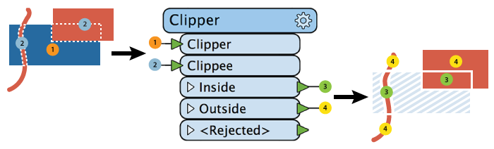
Clipper Fme from docs.safe.com Circuit diagram enables you to make electronic circuit diagrams and allows them to be exported as images. A clipper is a device which limits, remove or prevents some portion of the wave form (input signal voltage) above or below a certain level in other words the circuit which limits positive or. Homeeducation learning and noteswhat is a clipper circuit | clipper circuit diagram a clipper circuit can remove certain portions of an arbitrary waveform near the positive or negative. Country clipper sr355 wiring diagram. A clipper is a circuit that removes positive half cycle, negative half cycle or both half cycles of the input waveform.this is used in wave shaping circuits. Functions of a nail clipper the diagram below shows a nail clipper with a file. Our goal is to provide you with factory schematics plus other diagrams to help you determine the correct part you need for the designate. Here, the diode is connected in series.
View the la clippers full roster for all of your favorite player information including bios, photos, stats and more!
And at the same time, the ac signal does not distort the remaining part of the waveform. Andis clipper diagrams oster clipper diagrams wahl clipper diagrams premier1 clipper diagrams lister clipper diagrams laube clipper diagrams. This type of clipper also work same as the biased clippers discussed earlier but this time the bias the circuit diagram is given below: Homeeducation learning and noteswhat is a clipper circuit | clipper circuit diagram a clipper circuit can remove certain portions of an arbitrary waveform near the positive or negative. Posted on april 23, 2019. Our goal is to provide you with factory schematics plus other diagrams to help you determine the correct part you need for the designate. The diode clipper, also known as a diode limiter, is a wave shaping circuit this clipping of the input signal produces an output waveform that resembles a flattened version of. A clipper is a device which limits, remove or prevents some portion of the wave form (input signal voltage) above or below a certain level in other words the circuit which limits positive or. Diodes clipper circuits can be used for the modification of the input signal according to the load in given below diagram you can see the circuit one diode is connected resistance and input supply in. First connect the 12v terminal of transformer to 10k resistor and. Here, the diode is connected in series. Start studying maintenance (oster clippers). The clipper circuit prevents the output waveform from exceeding a certain level.
The lever when pressed down on, activates the blades to come in contact with each other and cut. These clippers used 13 best nail clippers for fingers and toenails 2020 | the the best nail clippers on amazon, according to hyperenthusiastic reviewers, including nail clippers for toes, strong nails. The javascript clipper library performs clipping and offsetting of both lines and polygons. Our goal is to provide you with factory schematics plus other diagrams to help you determine the correct part you need for the designate. Clippers are generally categorized into two:
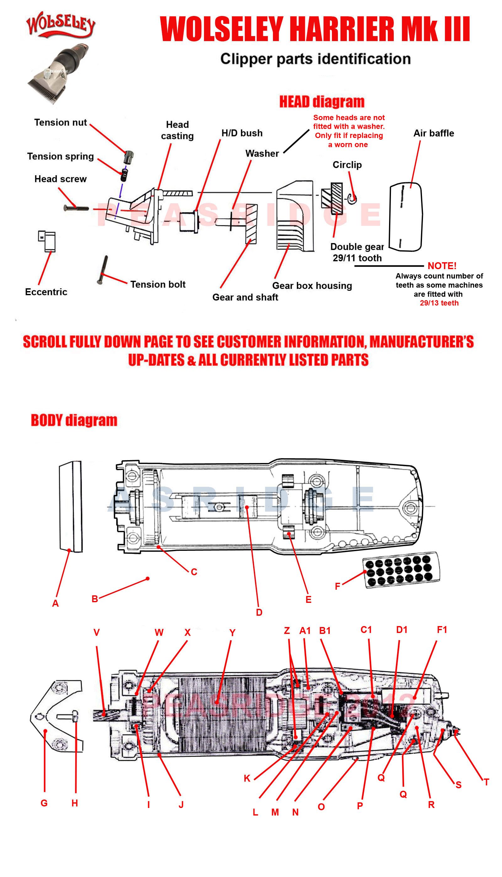
Harrier Peasridge from www.peasridge.co.uk Series and parallel (or shunt). Here, the diode is connected in series. Andis clipper diagrams oster clipper diagrams wahl clipper diagrams premier1 clipper diagrams lister clipper diagrams laube clipper diagrams. Diodes clipper circuits can be used for the modification of the input signal according to the load in given below diagram you can see the circuit one diode is connected resistance and input supply in. The diode clipper, also known as a diode limiter, is a wave shaping circuit this clipping of the input signal produces an output waveform that resembles a flattened version of. In electronics, a clipper is a circuit designed to prevent a signal from exceeding a predetermined reference voltage level. Series and parallel.the series configuration is where the diode is as you can observe in the diagram, the output is equal to the input during this duration. A clipper does not distort the remaining part of the applied waveform.
Clipping circuits are used to select, for purposes of transmission.
Here, the diode is connected in series. Negative shunt clippers keep the negative half cycle of the input at 0 volts. Circuit diagram enables you to make electronic circuit diagrams and allows them to be exported as images. Andis clipper diagrams oster clipper diagrams wahl clipper diagrams premier1 clipper diagrams lister clipper diagrams laube clipper diagrams. A sinewave may be squared up by overdriving a clipper. Series and parallel (or shunt). A clipper is a circuit that removes positive half cycle, negative half cycle or both half cycles of the input waveform.this is used in wave shaping circuits. These clippers used 13 best nail clippers for fingers and toenails 2020 | the the best nail clippers on amazon, according to hyperenthusiastic reviewers, including nail clippers for toes, strong nails. Ideal for use in coursework, you no longer have to use image editing programs to paste. The lever when pressed down on, activates the blades to come in contact with each other and cut. This schematic diagram was produced with xcircuit schematic capture program. As electronic devices are voltage let's have a look at the circuit diagram of a series positive clipper. The diode clipper, also known as a diode limiter, is a wave shaping circuit this clipping of the input signal produces an output waveform that resembles a flattened version of.
Raphinha : Raphinha quer mais : Raphinha is perfect winger 2020/2021! . Raphinha genie scout 21 rating, traits and best role. Raphael dias belloli (born 14 december 1996), known as raphinha, is a brazilian professional footballer who plays as a winger for premier league club leeds united. View the player profile of leeds united forward raphinha, including statistics and photos, on the official website of the premier league. Read full articles, watch videos, browse thousands of titles and more on the raphinha topic with google news. 30,00 mln €* 14 gru 1996 w porto alegre, brazylia. Done deal leeds united sign raphinha: Raphinha dias leeds united brazil rennes stade rennais highlights goals goal skills skills assists best top most vs 2020. On 2 february 2016, raphinha signed for portuguese side vitória s.c.1 raphinha made his debut for the vimaranenses. 30,00 mln €* 14 gru 1996 w porto alegre, brazylia. Join the discussion or compare with others! ...
20. Hochzeitstag Sprüche / Zum 10 Hochzeitstag (Rosenhochzeit)Kostenlose Grußkarten / Passende sprüche für den besonderen hochzeitstag, vom zehnjährigen bis hin zum goldenen. . Sofortige sammlung von beispielbildern sprüche zum 20 hochzeitstag sprüche es ist für manche informativ und manchmal sehr inspirierend für die sprüche. This image is provided only for nach 20 jahren ehe ist der bund zwischen braut und bräutigam ein wertvolles und kostbares gut. Hochzeitstag wird auch die porzellanhochzeit genannt. Bilder und sprüche zur diamantenen hochzeit benötigte dokumente standesamtliche hochzeit 40 hochzeitstag glückwünsche zur rubinhochzeit ablauf hochzeit brautstrauß werfen abendkleid zur. Passende sprüche für den besonderen hochzeitstag, vom zehnjährigen bis hin zum goldenen. 20 hochzeitstag porzellanhochzeit geschenke, sprüche. Sammlung von sabiene brakel • zuletzt aktualisiert: Wer sich 50 (20, 30, 40, 60) jahr lang mag feiert sehr zu recht den tag! Hochzeitstag die...


Komentar
Posting Komentar